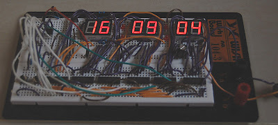
Now, I'm so crazy about led dot matrix clocks and led dot matrix watches. Just recently, I have upgraded my small 5x7 Led Dot Matrix Clock with a bigger green 5x7 led dot matrix display and a new font.
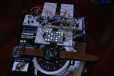
For the images below, the time 21:44:37 was displaying on the clock. The clock display is big comparing to a 44mm Panerai (PAM 4).


The code for the new font is showing below:
const unsigned char char2[][4]={
{0x0E,0x11,0x0E,0x00}, //0{0x09,0x1F,0x01,0x00}, //1{0x13,0x15,0x09,0x00}, //2{0x11,0x15,0x0A,0x00}, //3{0x1C,0x04,0x0F,0x00}, //4{0x19,0x15,0x12,0x00}, //5{0x0E,0x15,0x12,0x00}, //6{0x13,0x14,0x18,0x00}, //7{0x0A,0x15,0x0A,0x00}, //8{0x09,0x15,0x0E,0x00}, //9{0x0A,0x04,0x0A,0x00}, //Comma1{0x04,0x0A,0x04,0x00} //Comma2};


 Actually, I have made this long before the 5x7 led dot matrix clock. The clock utilizes a PIC16F627A and a 74HC595 to drive a small 8x8 Led Dot Matrix display (20x20mm). My dream is transforming these clocks to watches that I can ware on my wrist.