

You can use a PIC microcontroller and an LED matrix to create a binary clock (or if you prefer you can wire up individual LEDs).
This project uses an LED matrix block as it saves lots of wiring.
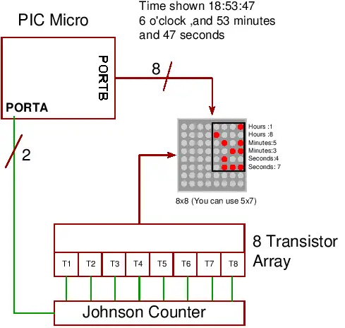
So what is it ?
Its an led clock that displays the time information as binary numbers...
...and it is a good way of learning how to read binary (well up to 9 any way!).
You can represent the numbers 0-9 using 4 binary digits so only four leds are needed for each time digit. There's a binary-decimal conversion table here.
To display hours, minutes and seconds (2 digits each) you need 6 binary digits in total (depending on whether you use a 24 hour clock the top digit needs only 1 or 2 LEDs).
(MSD,LSD Most Significant Digit, Least Significant Digit)
Note: You could use a 5x7 led matrix as only the right hand 4 leds (also only 6 rows) are used in this project.
The black rectangle, in the diagram above, shows which leds you need to look at - the rest are not used in this project. You read the clock starting from the top and read horizontal row of four LEDs as a binary number. Each LED that is on represents a one and each LED that is off represents a zero. You then use the conversion table to translate it into decimal until you become so good at it that you won't need the table!
I'll just say here that instead of using 64 output pins only 10 are needed to drive the display.

This project uses an LED matrix block as it saves lots of wiring.
So what is it ?
Its an led clock that displays the time information as binary numbers...
...and it is a good way of learning how to read binary (well up to 9 any way!).
You can represent the numbers 0-9 using 4 binary digits so only four leds are needed for each time digit. There's a binary-decimal conversion table here.
To display hours, minutes and seconds (2 digits each) you need 6 binary digits in total (depending on whether you use a 24 hour clock the top digit needs only 1 or 2 LEDs).
LED Binary Clock block diagram
How to read a binary clock
To show the time 6 digits are needed:Binary Clock digit defiinition
| Hours | MSD | 0-2 |
| Hours | LSD | 0-4 |
| Minutes | MSD | 0-5 |
| Minutes | LSD | 0-9 |
| Seconds | MSD | 0-5 |
| Secondss | LSD | 0-9 |
(MSD,LSD Most Significant Digit, Least Significant Digit)
Note: You could use a 5x7 led matrix as only the right hand 4 leds (also only 6 rows) are used in this project.
The black rectangle, in the diagram above, shows which leds you need to look at - the rest are not used in this project. You read the clock starting from the top and read horizontal row of four LEDs as a binary number. Each LED that is on represents a one and each LED that is off represents a zero. You then use the conversion table to translate it into decimal until you become so good at it that you won't need the table!
Hardware
This project uses the same hardware as the led matrix project using a 16F88 PIC microcontoller and an LED matrix. Its worth taking a look there as the same hardware description applies on how to multiplex the display.I'll just say here that instead of using 64 output pins only 10 are needed to drive the display.
PIC Microcontroller binary clock display hardware
(Click diagram to open a pdf)
(Click diagram to open a pdf)
PIC Micro Binary Clock Software
Project files for the dot matrix led display
Compiler project files
16F88-binary-clock.ppc
16F88-binary-clock.ppc
C Source files.
16F88-binary-clock.c
16F88-binary-clock.c
Header files.
types.h
bit.h
types.h
bit.h
Output files
16F88-binary-clock.hex
16F88-binary-clock.hex
Binary Clock code description.
16F88-binary-clock.c
This contains all the code except :
- Bit manipulation routines found in bit.h
- Type definitions in types.h
The code is simple to follow and everything is done in main().
The multiplexing method is the same for the led matrix project so have a look there for the software description of that method.
The only difficult part is to correctly control the time display but its not that difficult as you can see in the code.
Improvements
You can improve the project to make it into a full clock by adding a set of keys in the same way as the RTC project. This would let you set and change the time.PIC Microcontroller Accuracy
This project relies on the accuracy of the microcontroller's internal oscillator which is only 1% - and this is not very accurate at all. You can expect to loose ~15 minutes per day!
For a better accuracy use a crystal as shown in some of the other projects but note that it is difficult to create a very accurate clock.
Using a crystal oscillator you can make a clock that is accurate to a few minutes per month.
Note: Even when using a standard crystal the board layout is very important - i.e. it will be a lot better than 1% but won't be as good as watch crystal accuracy.
You could use a DS1307 clock chip but even these are hard to make accurate as they rely on a 32kHz crystal - end these are even more difficult to use effectively.
Binary clock accuracy| Clock source | Accuracy | Error per Day | Error per Month |
| Internal oscillator | 1% | 14 minutes | 7 hours |
| Standard crystal | 100ppm | 8.64 seconds | 4.32 minutes |
| Watch crystal | 20ppm | 1.73 seconds | 51 seconds |


